Extrude Command
The Extrude command in Siemens NX is one of the most fundamental tools for creating 3D geometry from 2D profiles. It allows you to extend a 2D sketch or curves into a 3D solid or sheet by adding depth in a specified direction. Here’s a complete breakdown of every detail and option available in the Extrude dialog box.
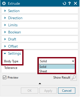
1. Type:
This option specifies the type of geometry the extrude command will create.
Solid Body: Creates a 3D solid from a closed 2D profile or sketch.
Sheet Body: Creates a surface (with no thickness) from a set of open or closed curves.
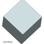
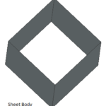
1. Select Curve:
1. Select Curve:
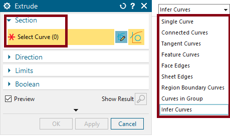
When using the Extrude command in NX, selecting curves is a crucial step to define the profile to extrude. NX provides a variety of curve selection options, allowing for precise control over the geometry. Here’s a breakdown of each option available under the Select Curve feature of the Extrude command:
Single Curve: ![]()
- Description: This option allows you to select individual curves for extrusion. The selected curve is extruded in the specified direction.
- Use Case: Ideal for extruding isolated sketches or independent segments that are not connected to other curves.
Connected Curves: ![]()
- Description: This option selects curves that are geometrically connected, forming a continuous chain. NX automatically recognizes and selects the entire connected chain of curves when you pick one curve.
- Use Case: Useful for extruding profiles that are composed of multiple connected curves, such as a closed loop forming a boundary.
Tangent Curves: ![]()
- Description: This option selects curves that are tangent to each other. When you select one curve, NX automatically selects all curves that share a tangential relationship, creating a smooth transition between them.
- Use Case: Best suited for creating extrusions from smooth, flowing curves like those found in automotive or aerodynamic designs.
Feature Curves: ![]()
- Description: Allows selection of curves that are derived from a specific feature. For example, edges of a solid feature that have been projected onto a sketch plane.
- Use Case: Ideal for reusing feature edges or curves generated by other operations without having to manually sketch them again.
Face Edges: ![]()
- Description: This option lets you select the edges of a solid face or sheet body. Instead of selecting drawn curves, you can select the edges that define a face.
- Use Case: Useful when you want to extrude edges from existing geometry, especially when creating additional features based on an existing body.
Region Boundary Curves: ![]()
- Description: Region boundaries are closed loops or connected curves that form the boundary of a region. Selecting this option will allow you to extrude the entire closed region formed by multiple curves.
- Use Case: This is particularly useful for creating extrusions from complex boundary shapes where multiple curves together define a region.
Curves in Groups: ![]()
- Description: This allows selection of multiple curves that have been grouped together in NX. Selecting one curve from the group automatically selects all curves within that group.
- Use Case: Useful when managing large sketches or assemblies where curves are grouped for organizational purposes, streamlining the extrusion process.
Infer Curve: ![]()
- Description: NX uses intelligent algorithms to infer the curves that should be selected based on proximity, relationships, and design intent. It can automatically detect nearby or relevant curves that fit the extrusion requirements.
- Use Case: Handy for quick extrusions when you are not concerned about manually selecting specific curves but want NX to infer the appropriate curves for the extrusion.
2. Direction:
Controls the direction in which the profile will be extruded.
Normal to Curve: By default, the extrusion occurs perpendicular to the profile’s sketch plane.
Select Vector: Allows you to define a custom vector or direction for the extrusion, useful for angled extrusions.
Select Edge as Direction: Lets you choose a linear edge from the model, and the extrusion follows this edge’s direction.
Specify Direction: Provides additional flexibility to extrude along a specific axis, plane, or user-defined direction.
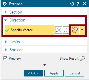
3. Start Limits :
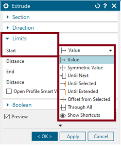
When using the Extrude command in NX, the start and end limit options define the extent of the extrusion along the specified direction. These settings provide control over the starting and ending points of the extrusion, allowing for precise modeling.
Here’s a breakdown of each start limit option:
Value:
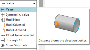
- Description: This option allows you to define a specific numerical value for the extrusion distance from the profile.
- Use Case: Best for situations where you know the exact distance you want the extrusion to start or extend from the profile.
- Example: If you want to extrude a profile by a precise 10 mm, you would enter “10 mm” as the start or end value.
Symmetric Value:
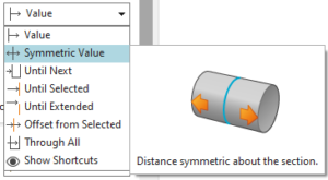
- Description: This option extrudes the profile symmetrically in both directions from the sketch plane. The distance specified is applied in equal amounts in both the positive and negative directions.
- Use Case: Ideal for centered extrusions where the profile needs to be extended equally in both directions.
- Example: If you set the value to 20 mm, the profile will be extruded 10 mm in both the positive and negative directions.
Until Next:
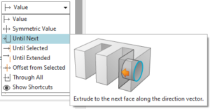
Description: The extrusion continues until it reaches the next face or body encountered along the direction of extrusion.
Use Case: Used when you want the extrusion to stop when it intersects another feature or body.
Example: You extrude a profile until it hits the next solid face, useful in part design for precise feature creation.
Until Selected:
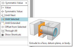
- Description: Allows you to select a specific face or body that the extrusion will extend to. The extrusion will stop at the selected geometry.
- Use Case: Useful when you want the extrusion to terminate at a pre-defined face or feature.
- Example: Extrude a sketch until it reaches a specific face of another body in an assembly.
Until Extended:
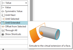
- Description: The profile is extruded until it intersects a selected face, even if the face needs to be conceptually extended for the extrusion to reach it.
- Use Case: When the selected face is not directly in line with the extrusion but extending the face will allow the extrusion to reach it.
- Example: You can extrude until it reaches an extended portion of a slanted face, even if the original face does not intersect the extrusion direction.
Offset from Selected:
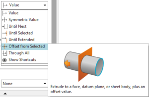
- Description: The extrusion begins or ends at an offset distance from a selected face or plane.
- Use Case: Useful when you need to maintain a specific gap between the extrusion and a reference face or plane.
- Example: Extrude a feature to start or stop 5 mm away from a selected face rather than directly on it.
Through All:
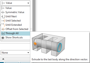
- Description: This option extrudes the profile through all existing geometry in the model, effectively cutting or extending through all bodies in the specified direction.
- Use Case: Ideal for operations like cutting holes or slots that need to pass completely through a part.
- Example: A hole extruded “Through All” will pass through the entire thickness of the part without requiring a specific termination point.
Additional Tips:
- Combining Options: You can mix start and end limit options to achieve more complex extrusions. For example, starting the extrusion with an offset and ending it “Until Next.”
- Preview Feature: Always use the preview option to visualize how the extrusion will behave before finalizing it, ensuring you achieve the desired result.
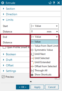
4. End Limits :
The Extrude command’s End Limit options in NX allow you to define how far the profile will be extruded from its starting point. These options provide flexibility in controlling the termination of the extrusion and are crucial for creating precise geometry.
Here’s a breakdown of each End limit option:
Value:
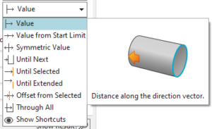
- Description: This option sets a specific numeric value for how far the profile will be extruded from the start point.
- Use Case: Best when you know the exact extrusion distance needed.
- Example: Entering a value of 20 mm will extend the extrusion exactly 20 mm from the start.
Value from Start Limit:
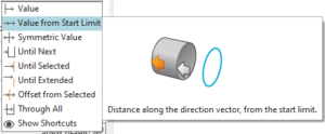
- Description: Allows you to specify the extrusion distance relative to the Start Limit. It takes into account the start limit’s value and adds this to define the total extrusion length.
- Use Case: Ideal when you want to control the overall extrusion distance based on where the start point is placed.
- Example: If the start limit is 10 mm and you enter 30 mm for the end limit, the extrusion will cover a total distance of 30 mm from the start.
Symmetric Value:
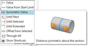
- Description: Extrudes symmetrically from the sketch plane, with the total distance split evenly in both directions.
- Use Case: Useful for centered or balanced extrusions where the profile must extend equally in both directions.
- Example: Setting a symmetric value of 40 mm will extrude 20 mm in one direction and 20 mm in the opposite direction.
Until Next:
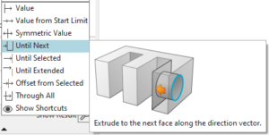
- Description: The extrusion will extend until it reaches the next face or body along the specified direction.
- Use Case: Useful for automatically terminating the extrusion when it intersects the next available surface.
- Example: Extruding a sketch until it hits the next face in an assembly, perfect for feature creation without manual dimensioning.
Until Selected:
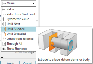
- Description: This option allows you to select a specific face, edge, or body that the extrusion will extend to.
- Use Case: Ideal when you need to terminate the extrusion at a particular pre-defined surface or object.
- Example: Extruding until a selected surface, such as stopping an extrusion at an angled plane.
Until Extended:
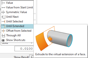
- Description: This option extends the extrusion until it intersects with a selected face, even if the selected face needs to be conceptually extended to reach the extrusion.
- Use Case: Useful when the selected face is not directly in line with the extrusion but extending it will cause the extrusion to reach it.
- Example: Extruding until an extended version of a slanted face that isn’t directly intersecting the extrusion.
Offset from Selected:
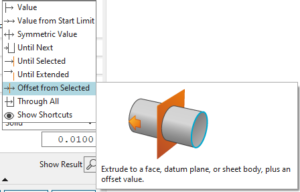
- Description: The extrusion will end at a specified offset distance from the selected geometry.
- Use Case: Handy when you want to maintain a specific gap between the extrusion and a reference face or feature.
- Example: Extrude a feature to end 5 mm away from a selected face rather than stopping exactly at it.
Through All:
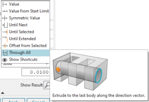
- Description: The extrusion passes through all existing geometry in the specified direction, cutting or extending through all bodies.
- Use Case: Ideal for operations like creating holes or slots that need to pass completely through a part.
- Example: A hole extruded Through All will pass through every solid body, ignoring the distance.
Tips for Effective use:
- Dynamic Preview: Always utilize the preview feature to visualize the extrusion before applying the operation.
- Combine Options: You can combine start and end limit options for complex extrusions, such as starting with an offset and ending with a Through All operation.
- Adjust as Needed: Use flexible end limit options like Until Next or Until Selected when dealing with assemblies or bodies with complex interactions.
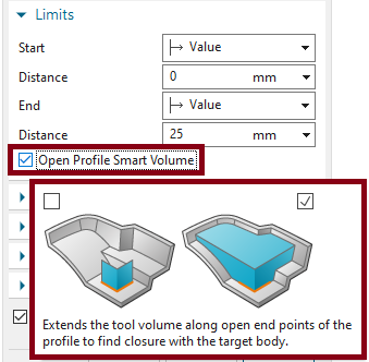
5. Open Profile Smart Volume :
The Extrude command in NX provides options for working with Open Profiles and introduces the Smart Volume feature to create a solid body from these open curves.
Here’s an explanation of when to tick and not tick the Smart Volume option.
Open Profile:
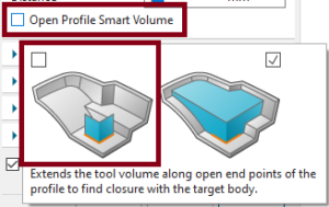
Description: An open profile is a sketch or set of curves that do not form a closed loop (e.g., an arc, an open spline, or a line). NX handles these differently from closed profiles, and how you extrude them depends on the desired outcome.
Behavior: Without closure, extruding open profiles usually creates surfaces unless specific features, like Smart Volume, are enabled to close the profile and generate solid geometry.
- Surface Creation: If you want to create a surface from an open profile (for trimming, thickening, or other surface-based operations), leave Smart Volume unchecked. The open profile will extrude as a surface, which can later be modified using surface modeling tools.
- Example: Extruding an open arc as a surface to later thicken it into a solid.
- No Nearby Geometry: When there is no nearby geometry or surfaces to interact with, and you don’t want NX to artificially close the profile.
- Partial Feature Extrusions: When you want to create just part of a feature and don’t need NX to attempt to close or extend the profile.
Practical Use Cases:
Smart Volume :
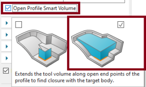
- Description: The Smart Volume option attempts to create a solid body from an open profile by closing gaps or extending edges intelligently to form a volume. It interacts with nearby geometry or extends the profile to enclose the shape during the extrusion process.
When to Tick (Enable) Smart Volume:
- Creating Solids from Open Profiles: Tick this option if you are extruding an open profile and want NX to automatically close the ends and form a solid. For example:
- If you have a U-shaped profile and want the open ends to be closed during the extrusion to form a block.
- When your open profile is part of a larger feature and you need it to create a solid volume.
- Merging with Existing Bodies: Use Smart Volume when extruding an open profile into an existing body, allowing NX to close the profile using the body’s faces.
- Complex Geometry: For more complex open sketches, Smart Volume helps avoid manual closing by automatically adjusting the edges to form a solid.
Practical Use Cases:
Additional Tips:
Preview: Always use the Preview option to visualize how NX handles the open profile and whether Smart Volume achieves the desired result.
Check Geometry: After using Smart Volume, verify that the geometry forms the solid shape you intend, especially when working with complex or irregular profiles.
7. Boolean Operation:
The Boolean options in the Extrude command of NX are critical for determining how the extruded geometry interacts with existing bodies in the model. They offer flexibility for creating, merging, cutting, or intersecting features.
Below is a detailed breakdown of each Boolean option:
1. None:
- Description: This option creates an extruded feature without performing any Boolean operation on existing bodies.
- Behavior: The result is a standalone feature that does not interact with other solid bodies in the model.
- Use Case: Use this when you want to create a new, separate part or surface without modifying the existing bodies.
- Example: Creating a surface or solid that will be used later in another operation, such as thickening or trimming.
2. Unite:
- Description: This option merges the extruded feature with an existing solid body.
- Behavior: The extrusion combines with any existing bodies it touches, forming a single continuous solid.
- Use Case: Ideal for adding material to an existing part, such as thickening a section, adding a new protrusion, or merging a rib with the main body.
- Example: Extruding a rectangular sketch into an existing block to create a larger, unified body.
3. Subtract:
- Description: The Subtract option removes material from existing solid bodies based on the extruded feature.
- Behavior: The extruded shape is subtracted from any intersecting solid bodies, creating a cut or hole.
- Use Case: Perfect for operations like creating holes, pockets, or cuts in an existing part.
- Example: Extruding a cylindrical sketch through a solid block to create a hole or cavity.
4. Intersect:
- Description: This option keeps only the volume that is shared between the extruded feature and the existing solid body.
- Behavior: NX generates geometry where the extrusion overlaps with an existing body, and any non-overlapping material is discarded.
- Use Case: Useful when creating intersecting features or cutting away everything except for the overlapping region of two solids.
- Example: Extruding a shape through a complex part and retaining only the intersected area for additional operations like joint creation.
5. Inferred:
- Description: The Inferred option allows NX to automatically determine the appropriate Boolean operation based on how the extruded feature interacts with existing geometry.
- Behavior: NX analyzes the model and applies either a Unite, Subtract, or Intersect operation depending on the geometry overlap.
- Use Case: This is useful when you’re unsure which Boolean operation is appropriate, or if you want NX to handle the interaction automatically for faster modeling.
- Example: Extruding a feature near a solid body, where NX decides whether to merge, cut, or intersect depending on the configuration.
Tips for Using Boolean Options:
- Visual Feedback: Always use the Preview feature to visualize how the Boolean operation will affect the model.
- Combine Options: You can use these Boolean options in combination with other extrude settings (such as Symmetric or Until Selected) for complex operations.
- Manual Control: When more precision is required, manually select the Boolean option that best fits your design intent, rather than relying on Inferred.
8. Draft:
Adds a draft angle to the sides of the extrusion for applications such as injection molds or cast parts.
Draft Angle: Specifies the angle of the draft. Positive values taper the extrusion inward, while negative values taper it outward.
Neutral Plane: Defines the plane from which the draft is applied.
Apply Draft to Both Sides: Applies the draft angle equally on both sides of the profile.
9. Advanced Section Control:
Allows for more complex control over the extrusion’s profile.
Offset Section: Shifts the profile before it is extruded. The offset can be positive or negative, moving the profile forward or backward in space.
Section Scaling: Lets you scale the profile during extrusion, allowing for tapered or non-uniform extrusions.
Profile Orientation: Controls how the profile is oriented as it is extruded. This can be useful for keeping certain features aligned with global axes or reference geometry.
10. Settings:
These settings control how the extrusion behaves in relation to the overall model.
Create Features: Enables feature history, allowing the extrude to be modified later. Disabling this option creates the extrusion as a permanent body without feature history.
Remove Self-Intersecting Geometry: Automatically removes regions where the extruded body might intersect with itself, ensuring clean geometry.
Material to Keep: Useful when using Subtract or Intersect operations, this option allows you to define which part of the material will be kept after the Boolean operation.
11. Output:
Defines whether the extrusion creates a solid or sheet body.
Solid: Creates a fully enclosed 3D solid.
Sheet: Creates a surface body without thickness. Useful for creating surfaces that will later be thickened or used in surface modeling.
12. Symmetry Options:
For symmetrical models or designs that require equal extrusion on both sides of a plane.
Symmetric About Plane: Extrudes the profile symmetrically about a plane, evenly distributing the extrusion on both sides.
Mirror: Automatically mirrors the extrusion across a specified plane, useful for symmetric part creation.
13. Preview and Visualization:
While setting up the extrude command, NX provides real-time preview options to visualize the result.
Dynamic Preview: Shows how the extrusion will appear based on your current settings. Any modifications will update in real-time.
Shaded or Wireframe Preview: Lets you toggle between shaded and wireframe modes for the preview, helping to visualize how the extrusion interacts with the existing model.
14. Endcap Options:
Controls how the ends of the extrusion are capped when the extrusion is not a full body.
Default Cap: Closes the ends of the extrusion with planar caps.
Open Ends: Leaves the ends of the extrusion open, which can be useful for surface modeling or certain sheet metal designs.
Additional Tips for Using the Extrude Command:
Boolean Operations: Use Unite, Subtract, and Intersect effectively for combining or modifying existing bodies.
Drafts and Tapers: These are crucial for ensuring manufacturability, especially in processes like Gravity Die Casting, HPDC , Sand molding where parts need to be removed from molds.
Offset Section: Use this to fine-tune the position of the extrusion without changing the base profile.

